The solenoid assembly in 5 steps
Menu
Part 1
Part 2
Part 3
Part 4
Part 5
Step 1 of 5
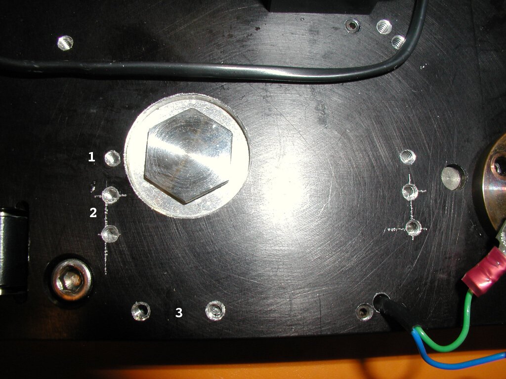
- This and the corresponding one off to the right are new
holes drilled to move the screw assembly up a bit, to make room
for the dial indicator mount.
- These four are the original holes for the screw
assembly.
- This is where you mount the dial indicator.
Back to the menu
Step 2 of 5
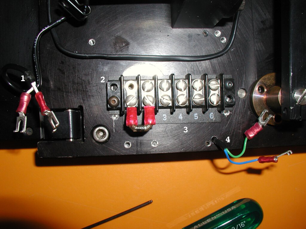
- These hook up to the solenoid controller, so the order
doesn't matter. Screw them into 1 and 2.
- The board with the screws. Pretty self-explanatory.
- Screw this on underneath the screw board to number the
slots.
- Hooks up to the filter wheel limiter lever (This guy). These go
in slots 5 and 6.
Back to the menu
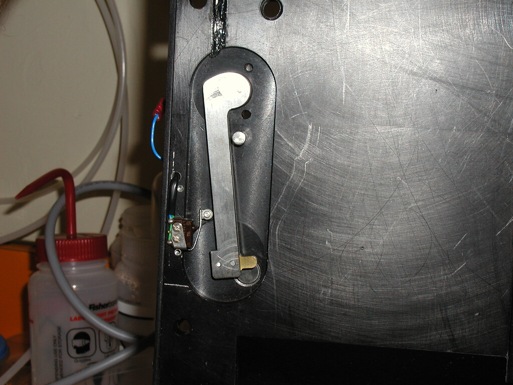
Step 3 of 5
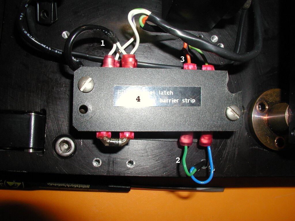
- From the solenoid. Goes into 1 and 2.
- From the limit lever. Goes into 5 and 6
- From the encoder. Goes into the other side of 5 and
6.
- The cover panel. A little rough around the edges, but just
screw it on as best you can!
Back to the menu
Step 4 of 5

- The encoder circuitry. Just mount it into the slot.
- The solenoid. Best not to take this guy off if at all
possible, because realigning it is a gigantic pain.
- This will tell you where to put the wires if you take them
off.
Back to the menu
Step 5 of 5
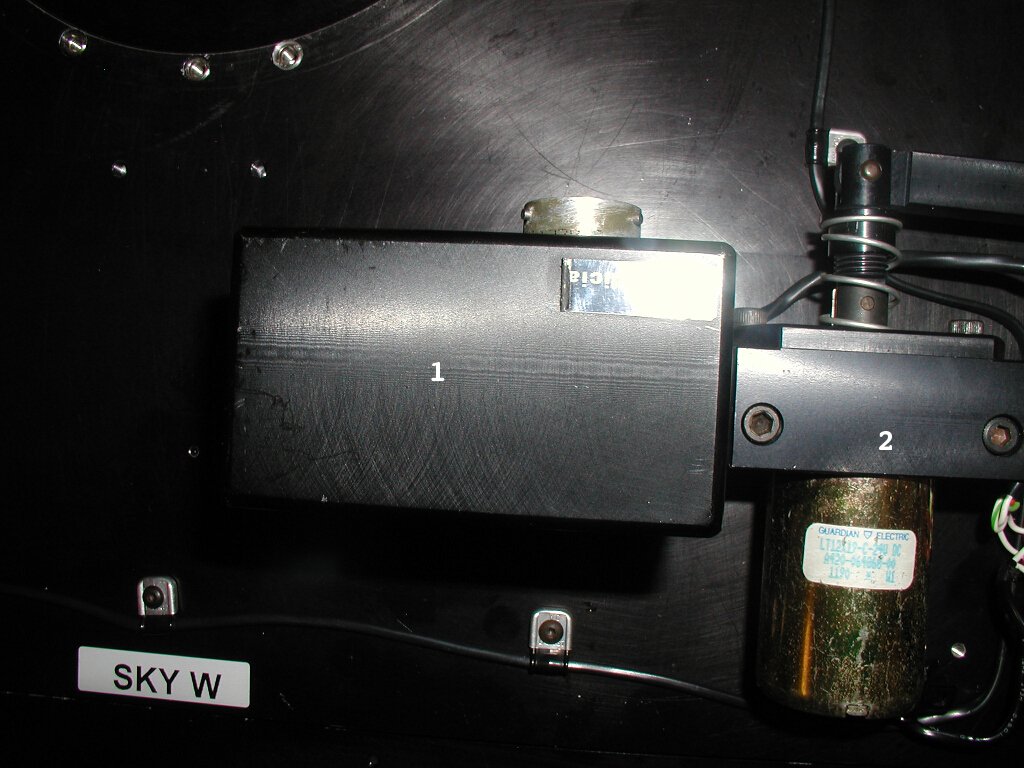
- The box to put over the encoder. Just scrunch up the wires
and jam it on there. It'll be fine.
- The solenoid. See the previous step.
Back to the menu
Back to the main page
Back to the base plate menu